
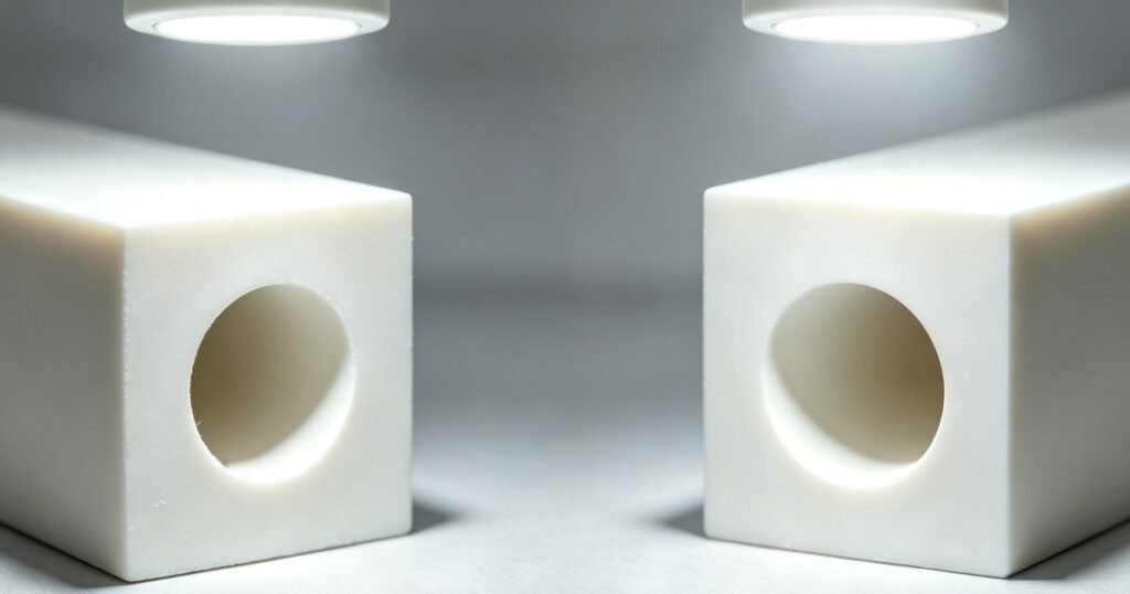
Ceramic machining of sintered technical ceramics relies almost exclusively on diamond abrasives, and the quote for a ceramic part is set by two things: how many faces need diamond time, and how tight each of those faces has to be. Most of a ceramic part is shaped before the furnace, when the compact still cuts with carbide tools; only the functional surfaces that need real precision go under diamond after firing. This guide covers the three machining states, the methods available on fully sintered parts, the tolerances each state actually holds, and the drawing decisions that decide the cost. Material data on alumina, zirconia, silicon nitride, and silicon carbide is drawn from our material data sheet. For finecer's in-house equipment and capabilities, see our ceramic CNC machining page.
The Three Machining States Set Everything Downstream
Ceramic parts are machined in one of three states, and the choice sets cost, achievable tolerance, and lead time in a way no downstream step reverses.
| State | Tool | Removal rate | Achievable tolerance | Relative cost |
|---|---|---|---|---|
| Green (unfired powder compact) | Carbide, HSS | High, similar to machining chalk | ±1 to 3% after sintering | 1x |
| Bisque or pre-sintered | Carbide, CVD-diamond coated | Medium | ±0.5 to 1% after final sinter | 2x |
| Fully sintered | Diamond abrasive only | Low, far below metal cutting rates | ±0.05 mm down to ±0.001 mm | 5x to 20x |
The forming route is what decides how much diamond time a part will need. Ceramic injection molding ships near net shape and often needs only light grinding on functional faces. Cold isostatic pressing sits in the middle, uniform density across the blank makes shrinkage predictable but still leaves 1 to 2% of dimension to grind. Dry pressing gives simple shapes at volume and typically needs the most post-sintering work because density gradients across the compact translate into local warp after firing.
Sintering shrinkage is around 15 to 20% by linear dimension, and it is not perfectly uniform. That is why green-machined features cannot hold better than about ±1% without a grinding pass after the furnace, and why the drawing should say which features can live with that and which cannot.
Ceramic Machining Methods for Sintered Parts
Once a ceramic is fully sintered, it is shaped and finished by diamond abrasive processes, not by conventional cutting. The right method depends on the feature, not on the shop's preference.
| Feature | Method | Typical Ra |
|---|---|---|
| Flat face, tight parallelism | Surface grinding | 0.8 to 1.6 μm |
| Outer diameter, tight roundness | Cylindrical or centerless grinding | 0.8 to 1.6 μm |
| Bore, blind or through | Internal grinding, diamond honing | 0.8 to 1.6 μm |
| 3D pockets, contours, complex geometry | Diamond CNC milling | 0.8 to 0.4 μm |
| Ultra-flat, optical or sealing | Lapping and polishing | ≤ 0.1 μm |
| Thin slices, wafers, chips | Diamond wire saw, dicing | Kerf-dependent |
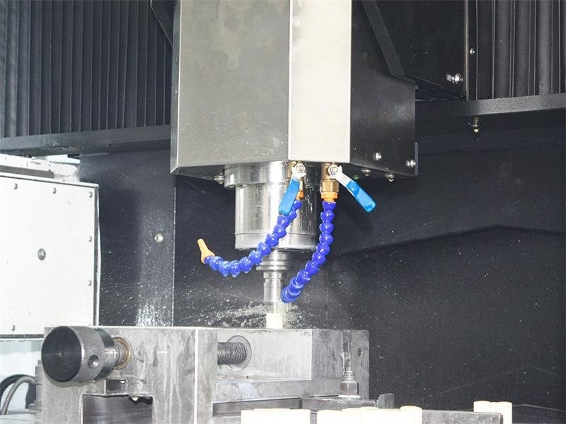
Two methods appear on generic lists but do not apply to most technical ceramics. Electrical discharge machining requires a conductive workpiece, and alumina, zirconia, and silicon nitride all sit above 1012 Ω·cm volume resistivity, so EDM is off the table for them. Laser cutting handles thin sections and 2D contours cleanly but deposits a heat-affected zone that can seed microcracks in load-bearing parts, so it stays a specialty route for slotting, marking, and preforming. Diamond grinding, milling, lapping, and polishing cover the vast majority of production sintered ceramic parts.
How Material Choice Changes the Machining Bill
Hardness sets how fast the diamond wheel can cut, and fracture toughness sets how aggressively the process can push before the edge chips. Together they decide the machining bill for a given geometry.
| Material | Hardness (HV0.5) | Fracture toughness (MPa·m½) | Flexural strength (MPa) | Effect on machining |
|---|---|---|---|---|
| Alumina 99% | ≥1500 | 4.2 | 346 | Baseline grinding cost. Higher purity grades machine slightly slower. |
| Zirconia | ≥1200 | 9.18 | 631 | Softest of the four, but low thermal conductivity (1.2 to 3.0 W/m·K) traps grinding heat and can trigger surface phase transformation if parameters are wrong. |
| Silicon nitride | ≥1400 | 8.16 | 812 | High toughness allows more aggressive parameters, and diamond wheel life on Si3N4 is better than on SiC. |
| Silicon carbide | ≥2100 | 4.85 | 415 | Hardest of the common technical ceramics. Grinding is noticeably slower than alumina at the same wheel spec, and wheel wear is higher. |
The takeaway is that material choice is a machining decision as much as a functional one. Specifying silicon carbide for a decorative or non-contact feature carries a machining premium that the application does not repay, but the same choice for a semiconductor plasma-facing part is correct because few alternatives match its plasma and wear resistance in that duty. Full six-grade alumina data sits on our alumina properties data hub.
Achievable Ceramic Machining Tolerances, and How They Are Verified
Achievable tolerance on a ceramic part depends on which state the feature is finished in, not on a single number that applies to the whole drawing.
| Finish state | Linear tolerance | Surface Ra | Roundness or form |
|---|---|---|---|
| As-fired, CIP or dry press | ±1 to 2% of dimension, or ±0.2 mm minimum | Typically 1.6 μm or finer | 1 to 2% of diameter |
| As-fired, injection molded | ±0.5 to 1% of dimension | Typically 0.8 μm or finer | 0.5 to 1% of diameter |
| Diamond ground, standard | ±0.05 mm | 0.4 μm | 0.05 mm |
| Diamond ground, precision | ±0.005 mm | 0.2 μm | 0.005 mm |
| Ground and polished, precision (finecer) | ±0.001 mm | 0.1 μm | ≤ 0.002 mm, verified on a ±0.0001 mm roundness tester |
Rows 1 to 4 are industry-typical figures. The last row reflects finecer's in-house capability on selected features, not a whole-part guarantee.
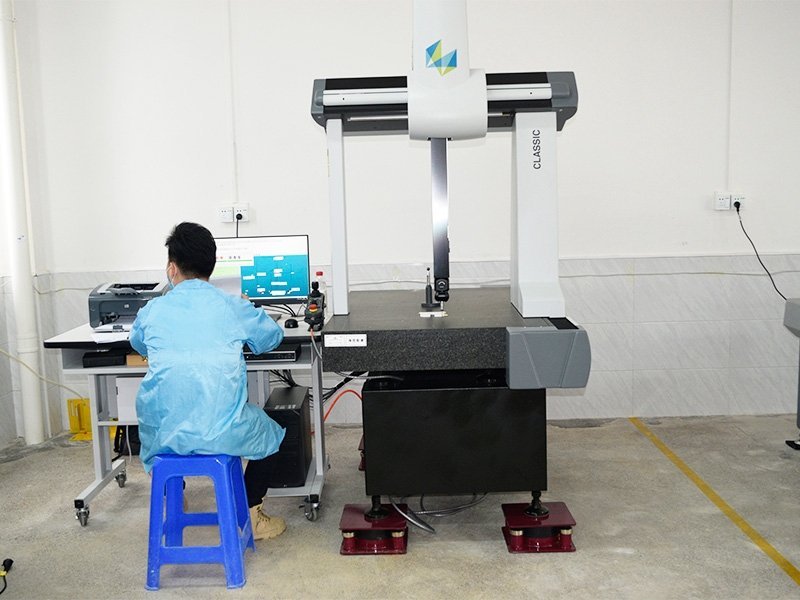
Quoted tolerance turns into delivered tolerance at inspection. finecer's inspection line runs CMM to ±0.001 mm resolution, roundness measurement to ±0.0001 mm, surface profilometry to 0.001 μm resolution, and Archimedes density verification against each grade's minimum density specification on every batch. Every shipment carries the actual measured values against each drawing callout, alongside the material certificate and batch traceability number. The published detail sits on the quality control page. This is the difference between a supplier who says the tolerance was met and one who ships the measurement that proves it.
What Drives Ceramic Machining Cost
The three variables that decide a ceramic machining quote are how many faces need diamond time, how tight each of those faces needs to be, and how much of the part is left as-fired.
- Number of ground faces. Every functional surface added to the drawing is a separate setup on the grinding line, and setup dominates cycle time on small batches.
- Tolerance level. In our quoting experience, going from ±0.05 mm to ±0.005 mm on a single diameter can roughly double the cost of that feature. Tightening further to ±0.001 mm roughly doubles it again.
- Threshold jumps. Cost is not continuous. If one dimension forces a feature from as-fired to standard ground, the setup cost of adding grinding to that feature lands whether the tolerance called out is ±0.05 mm or ±0.02 mm.
- Material. Silicon carbide grinding runs slower than alumina and wears wheels faster. Zirconia is close to alumina on cost but needs heat control during grinding.
- Feature difficulty. Small bores, deep pockets beyond 5:1 depth-to-diameter, thin walls, internal sharp corners, and internal threads either raise cost sharply or force a design change.
- Quantity. Setup amortizes across the batch. A one-piece prototype can cost several times the per-unit price of the same part in a production run.
- Inspection level. Per-piece CMM reporting adds cost over batch-based sampling. Regulated industries usually require it, most industrial applications do not.
How to Tolerance a Ceramic Drawing
Tolerance only the features that need it, mark everything else as-fired, and put the rule in the title block. This one drawing discipline changes ceramic machining quotes more than any other single decision.
| Functional feature (tighten) | Typical callout | Non-functional feature (leave as-fired) |
|---|---|---|
| Sealing face | Ra ≤ 0.1 μm, flatness per drawing | Non-mating flat face |
| Bearing bore, pin hole, locating diameter | Diameter to fit class, roundness ≤ 0.005 mm | Clearance hole with ≥ 0.5 mm gap |
| Locating outer diameter | Diameter to fit class, cylindricity ≤ 0.01 mm | Outer diameter inside a housing with clearance |
| Reference edge or datum face | Perpendicularity per drawing | Cosmetic or draft face |
| Electrode or contact face | Flatness and Ra per drawing | Part backside not in the circuit |
The default rule that works for most ceramic drawings is simple. Individually toleranced features carry their own callout. The title block reads something like "General tolerance: as-fired, ±1% of dimension or ±0.2 mm, whichever is greater." A drawing that puts every dimension in a ±0.05 mm block will be quoted as if every surface must be ground, and the number will reflect that. Marking three features tight and leaving the other fifteen dimensions as-fired typically cuts a quote by half or more in our quoting experience, without changing the part's fit or function.
Design Limits: What Can and Cannot Be Machined
Ceramic machining has geometric limits that thread milling on aluminum does not, because brittleness sets a minimum feature scale below which the part chips or cracks during processing.
| Feature | Practical minimum |
|---|---|
| Through hole diameter | ~0.7 mm by diamond core drilling, deeper than 5x diameter needs DFM review |
| Blind hole depth-to-diameter | 5:1 without specialty tooling |
| Wall thickness | ~0.5 mm on parts under 20 mm, thicker on larger parts |
| Internal sharp corner | Add radius ≥ 0.5 mm, sharp internal corners crack under load |
| External thread | Groundable, larger pitch preferred |
| Internal thread | Usually replaced with a pressed or brazed metal insert |
| Slot width | ≥ 0.3 mm, set by diamond blade or wheel width |
These values are the points where the process gets expensive or unreliable, not hard stops. A 0.3 mm through hole in alumina is possible with laser drilling, but the cost profile changes. When a drawing pushes several limits at once, a design-for-manufacturability discussion before quotation saves iteration cycles.
What to Send with an RFQ
A ceramic machining quote gets more accurate and closer to the real cost when the RFQ includes six things, in this order.
- 2D drawing with tolerances called out per feature, plus 3D model (STEP preferred).
- Material and purity grade, or the environment the part will see if the grade is open for discussion.
- Which faces are functional, marked on the drawing or listed separately.
- Surface roughness in Ra, only on the features that need it.
- Prototype, pilot, and production quantities, listed separately so the quote does not optimize the wrong stage.
- Inspection requirements: batch-based or per-piece, and any regulated-industry documentation.
For custom geometries, non-standard materials, or single-piece prototypes, the custom ceramic parts intake walks through the same checklist. Standard RFQ response is within 24 hours, and a 1-piece sample runs the full production chain (forming, sintering, machining, and inspection) with the measured report attached.